Shop Time Part 7 - CAD Agent
Posted on August 10, 2026 by Michael Keane Galloway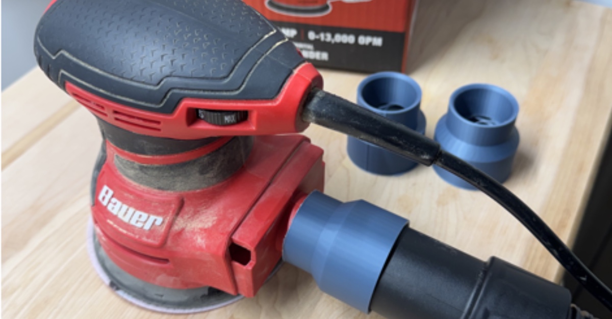 I’ve written previously about issues that I’ve had with using an orbital sander
due to my wrists. One of the key things that I’ve done to manage this is to
limit how much sanding I do, and if that slows down the project then that’s
just the way it has to be.
I’ve written previously about issues that I’ve had with using an orbital sander
due to my wrists. One of the key things that I’ve done to manage this is to
limit how much sanding I do, and if that slows down the project then that’s
just the way it has to be.
With limitations on sanding time, I also looked at how I can make my sanding more efficient. That way I can get more sanding done in the time hat I have. One solution that I found online was to use mesh sanding disks instead of the standard paper disks. These are more expensive but the mesh design allows for more air flow through the sander resulting in more dust getting sucked into the dust tray of the sander. This improves sander efficiency by removing the dust from the piece, which in turn means that the abrasive in the sanding pad can do more work directly on the piece.
Another way to improve this efficiency would be to remove the sanders dust bin and replace it with a shop vac. Having a vacuum attached to the orbital sander accelerates dust collection and provides a much larger volume for dust to be collected over the stock dust bin. The problem that I faced with that is my sander and my shop vac are built by two different manufacturers and there was no easy way to hook them together.
I really wanted a plastic shop vac adapter that would friction fit the shop vac hose to the orbital sander dust exhaust. Thankfully as of last November, I have a 3D printer. Unfortunately, I hadn’t touched CAD since high school and a lot of things have changed. Then while participating in a AI project competition at work, I had an idea. What if I built an agent to help me with CAD. That way I can feed in measurements and ideas to get a 3D printable model.
I set about making skills for Claude to help automate the creation of these models. The idea was to have these skills focus on generating Python scripts that would drive FreeCAD in headless mode. That way I could have an audit-able process since the agent produces code that I can read. This Python script when run, then builds a parametric model (basically a model driven by a spreadsheet; update a cell and the 3D model changes on the fly) in FreeCAD that I can then review before exporting it to the slicer for printing.
One of the key design choices here was that I wanted multiple points of control without having to go back to the agent and spend more tokens. Having a Python script that’s readable lets me potentially tweak things myself. Then having that script produce a parametric model means that if I want to tweak something small, I can update relevant values in FreeCAD. I also have abilities to edit the model further for printing in the slicer. This way I have multiple efficient ways to update the work without having to use AI resources.
Having the multiple points of control helped several problems that I had once I was printing the part. The first was that there was too little overlap between the main cylinders of the part, which led to a failed print. That had to be solved by going all the way back to Claude for a refinement.
The next issue I faced was that print orientation resulted in an unsupported cantilever. This cause print quality issues as the 3D printer attempted to place plastic in the air. The solution to this was 2 fold. I went back to the agent to get a chamfer around the outside of the part by fusing a cone to the solid. Once that was created I then had to use the slicer to change the print orientation so that the smaller cylinder that connects with the sander would be in contact with the build plate in order to allow the chamfer to support the larger cylinder for the hose side of the adapter.
With changing the print orientation, I then had a problem with adherence to the build plate. We had a much smaller circle of contact. There was also a chamfer on each side adapter to help with fitting each end that decrease the contact with the build plate further. The solution to this was to add a brim on the outside of the adapter so there was extra plastic holding the part to the build plate. This brim then also necessitated some physical post processing since I then had to deburr the area where the brim was attached.
After all of that, the friction fit wasn’t very good on the vacuum hose. That required me to go back to the parametric model to quickly change the diameter of the shop vac side of the adapter. Then after a quick reprint, I had a functional part. I then tested it by sanding down some stains on an old kitchen island that I repurposed for my 3D printer table.
The files for this can be found on Printables: https://www.printables.com/model/1695972-parametric-shop-vac-sander-adapter-adapter
This is the python script that I generated:
import FreeCAD
import Part

doc = FreeCAD.newDocument("SanderVacAdapter")

# --- Parameters (Spreadsheet) ---
sheet = doc.addObject("Spreadsheet::Sheet", "Parameters")

# Primary parameters
sheet.set("A1", "sander_od");        sheet.set("B1", "34.0");   sheet.setAlias("B1", "sander_od")
sheet.set("A2", "vac_od");           sheet.set("B2", "44.75");  sheet.setAlias("B2", "vac_od")
sheet.set("A3", "sander_clearance"); sheet.set("B3", "0.3");    sheet.setAlias("B3", "sander_clearance")
sheet.set("A4", "vac_clearance");    sheet.set("B4", "0.3");    sheet.setAlias("B4", "vac_clearance")
sheet.set("A5", "wall");             sheet.set("B5", "3.0");    sheet.setAlias("B5", "wall")
sheet.set("A6", "sander_len");       sheet.set("B6", "25.0");   sheet.setAlias("B6", "sander_len")
sheet.set("A7", "vac_len");          sheet.set("B7", "25.0");   sheet.setAlias("B7", "vac_len")
sheet.set("A8", "chamfer_w");        sheet.set("B8", "1.5");    sheet.setAlias("B8", "chamfer_w")
sheet.set("A9", "overlap");          sheet.set("B9", "1.0");    sheet.setAlias("B9", "overlap")

# Derived parameters (spreadsheet formulas — keeps geometry expressions simple)
sheet.set("A10", "sander_id");       sheet.set("B10", "=B1 + 2 * B3");    sheet.setAlias("B10", "sander_id")
sheet.set("A11", "vac_id");          sheet.set("B11", "=B2 + 2 * B4");    sheet.setAlias("B11", "vac_id")
sheet.set("A12", "sander_inner_r");  sheet.set("B12", "=B10 / 2");        sheet.setAlias("B12", "sander_inner_r")
sheet.set("A13", "vac_inner_r");     sheet.set("B13", "=B11 / 2");        sheet.setAlias("B13", "vac_inner_r")
sheet.set("A14", "sander_outer_r");  sheet.set("B14", "=B12 + B5");       sheet.setAlias("B14", "sander_outer_r")
sheet.set("A15", "vac_outer_r");     sheet.set("B15", "=B13 + B5");       sheet.setAlias("B15", "vac_outer_r")
sheet.set("A16", "total_len");       sheet.set("B16", "=B6 + B7");        sheet.setAlias("B16", "total_len")
sheet.set("A17", "vac_body_h");      sheet.set("B17", "=B7 + B9");        sheet.setAlias("B17", "vac_body_h")
sheet.set("A18", "sander_body_h");   sheet.set("B18", "=B6 + B9");        sheet.setAlias("B18", "sander_body_h")
sheet.set("A19", "sander_body_z");   sheet.set("B19", "=B7 - B9");        sheet.setAlias("B19", "sander_body_z")
sheet.set("A20", "chamfer_vac_r1");  sheet.set("B20", "=B13 + B8");       sheet.setAlias("B20", "chamfer_vac_r1")
sheet.set("A21", "chamfer_sand_r2"); sheet.set("B21", "=B12 + B8");       sheet.setAlias("B21", "chamfer_sand_r2")
sheet.set("A22", "chamfer_sand_z");  sheet.set("B22", "=B16 - B8");       sheet.setAlias("B22", "chamfer_sand_z")

# Transition chamfer: slopes outer wall from vac_outer_r down to sander_outer_r at the step
sheet.set("A23", "transition_h");    sheet.set("B23", "8.0");             sheet.setAlias("B23", "transition_h")
sheet.set("A24", "transition_z");    sheet.set("B24", "=B17");             sheet.setAlias("B24", "transition_z")

doc.recompute()

# --- Outer body ---
# Vac-end outer cylinder (larger diameter), positioned at z=0
vac_body = doc.addObject("Part::Cylinder", "VacBody")
vac_body.setExpression("Radius", "Parameters.vac_outer_r")
vac_body.setExpression("Height", "Parameters.vac_body_h")

# Sander-end outer cylinder (smaller diameter), overlaps vac end by 'overlap' to guarantee solid union
sander_body = doc.addObject("Part::Cylinder", "SanderBody")
sander_body.setExpression("Radius", "Parameters.sander_outer_r")
sander_body.setExpression("Height", "Parameters.sander_body_h")
sander_body.setExpression("Placement.Base.z", "Parameters.sander_body_z")

# Transition cone: slopes outer wall from vac_outer_r (bottom) to sander_outer_r (top)
# Sits just below the step at z=vac_body_h, adding material to the shoulder and reducing the
# abrupt step that causes stringing in FDM prints.
transition_cone = doc.addObject("Part::Cone", "TransitionCone")
transition_cone.setExpression("Radius1", "Parameters.vac_outer_r")
transition_cone.setExpression("Radius2", "Parameters.sander_outer_r")
transition_cone.setExpression("Height", "Parameters.transition_h")
transition_cone.setExpression("Placement.Base.z", "Parameters.transition_z")

# Fuse the two stepped cylinders, then fuse in the transition cone
step_fuse = doc.addObject("Part::Fuse", "StepFuse")
step_fuse.Base = vac_body
step_fuse.Tool = sander_body

fuse1 = doc.addObject("Part::Fuse", "OuterBody")
fuse1.Base = step_fuse
fuse1.Tool = transition_cone

# --- Inner bores ---
# Vac bore through the vac socket (z=0 to z=vac_len)
vac_bore = doc.addObject("Part::Cylinder", "VacBore")
vac_bore.setExpression("Radius", "Parameters.vac_inner_r")
vac_bore.setExpression("Height", "Parameters.vac_len")

# Sander bore through the sander socket (z=vac_len to z=total_len); shoulder limits insertion depth
sander_bore = doc.addObject("Part::Cylinder", "SanderBore")
sander_bore.setExpression("Radius", "Parameters.sander_inner_r")
sander_bore.setExpression("Height", "Parameters.sander_len")
sander_bore.setExpression("Placement.Base.z", "Parameters.vac_len")

# Subtract vac bore from outer body
cut1 = doc.addObject("Part::Cut", "Cut1")
cut1.Base = fuse1
cut1.Tool = vac_bore

# Subtract sander bore
cut2 = doc.addObject("Part::Cut", "Cut2")
cut2.Base = cut1
cut2.Tool = sander_bore

# --- Entry chamfers (truncated cones ease tube/hose insertion at each opening) ---
# Vac-end chamfer: widens the opening at z=0 (Radius1 > Radius2 so it flares outward at the base)
vac_chamfer = doc.addObject("Part::Cone", "VacChamfer")
vac_chamfer.setExpression("Radius1", "Parameters.chamfer_vac_r1")
vac_chamfer.setExpression("Radius2", "Parameters.vac_inner_r")
vac_chamfer.setExpression("Height", "Parameters.chamfer_w")

# Sander-end chamfer: widens the opening at z=total_len (Radius2 > Radius1 so it flares at the top)
sander_chamfer = doc.addObject("Part::Cone", "SanderChamfer")
sander_chamfer.setExpression("Radius1", "Parameters.sander_inner_r")
sander_chamfer.setExpression("Radius2", "Parameters.chamfer_sand_r2")
sander_chamfer.setExpression("Height", "Parameters.chamfer_w")
sander_chamfer.setExpression("Placement.Base.z", "Parameters.chamfer_sand_z")

# Subtract vac-end chamfer
cut3 = doc.addObject("Part::Cut", "Cut3")
cut3.Base = cut2
cut3.Tool = vac_chamfer

# Subtract sander-end chamfer — this is the final result
result = doc.addObject("Part::Cut", "Result")
result.Base = cut3
result.Tool = sander_chamfer

# --- Recompute and save ---
doc.recompute()
doc.saveAs("cad-output/sander-vac-adapter.FCStd")
print("Saved: cad-output/sander-vac-adapter.FCStd")